Ducting is a main and important component of any clean air system design. Ducting involves various parameters, including ducting type, required velocity, power consumption, and pressure drop. We will discuss all the above parameters in today's blog post, “Duct Design: Guide for Ducting Design of a Clean Air System," as well as a few guidelines for standard duct design.
Ducting has two types:
Duct type, such as round or spiral duct, is a type of steel pipe made from various materials like stainless steel, aluminum, copper, and galvanized steel.
Round ducts are more common in fume extraction and dust collection systems, whereas rectangular ducts are more common in air conditioning systems and fresh air ventilation systems.
The main reason is that the dust accumulation inside round ducts is very low as compared to rectangular ducts. In rectangular ducts, dust keeps getting accumulated at the corners. This is not a good situation in any way because it creates a safety or fire hazard in the case of some industrial pollutants like aluminum dust and where there is a possibility of sparks or hot particles entering the duct. Other factors are:
Certain optimum ranges are recommended as per application; e.g., for dust collector applications, a range of 20–22 m/s is common so as to avoid dust deposition inside the duct. This velocity ensures that most of the dust particles are swept effectively up to the dust collector. In the case of welding fumes, this value is lower (@15–17 m/s), as it would need much less velocity to convey fumes as compared to dust.
CFM, which is “cubic feet per minute,” = velocity, which is shown in “feet per minute,” multiplied by the area, which is shown in “square feet.”
Duct Sizing:
Duct sizing is the most important factor in the design of a duct.
How is the duct size calculated then?
The Darcy equation reveals that reducing duct diameter increases pressure loss at a constant volume flow rate, while larger volume flow rates require larger duct diameters.
Duct Sizing Methods:
There are three important duct-sizing methods:
Duct velocity and pressure drop are important factors in a clean-air system. These factors influence airflow, duct velocity, and total pressures. Accurate calculations help ensure optimal airflow, comfort, and efficient system design. Excessively higher velocities than the recommended range would produce a very high pressure drop. Also, too little velocity will increase the size of the duct and, thus, the ducting cost.
Higher velocity leads to a higher pressure drop, and thus, you would need more power to overcome that pressure drop. This will increase the running cost of the system.
Increasing and decreasing diameters in duct sizing are based on the Darcy equation. The Darcy equation reveals that reducing duct diameter increases pressure loss at a constant volume flow rate, while larger volume flow rates require larger duct diameters.
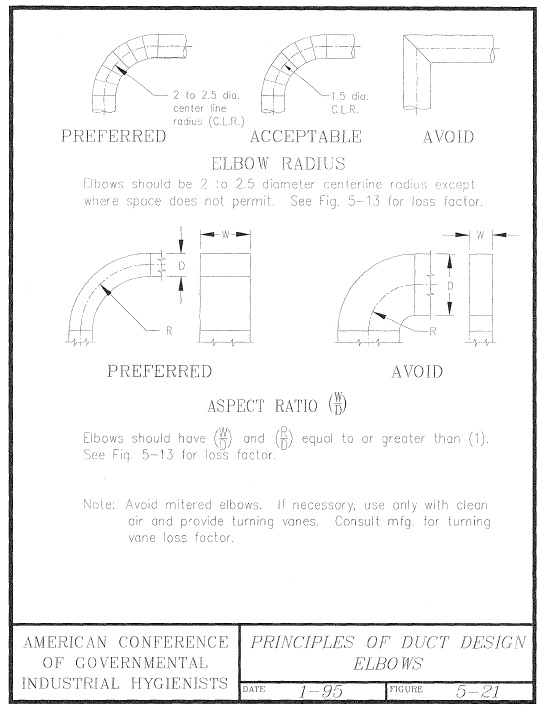
Elbows:

Fig: Principles Of Duct Design-Elbows(ACGIH Industrial Ventilation-23 Edition)
Radius elbows are recommended for rectangular ducts, while mitered elbows with turning vanes are suitable for medium- and high-velocity VAV systems. Short-radius elbows with splitters are recommended for medium- and high-velocity systems. Mitered elbows with turning vanes are used if necessary, but not for low-velocity systems.
Sharp Bends:
Avoid sharp bends or turns to make the air flow clear, because sharp bends or turns restrict the air flow speed in ducting.
The ductwork system utilizes various types of bends, including long radius bends with a gradual centerline radius, short radius bends with a sharper radius, and U-shaped bends like return bends. Mitered bends, offset bends, and bumper bends are used to change flow direction, redirect flow, and absorb shock or vibration.
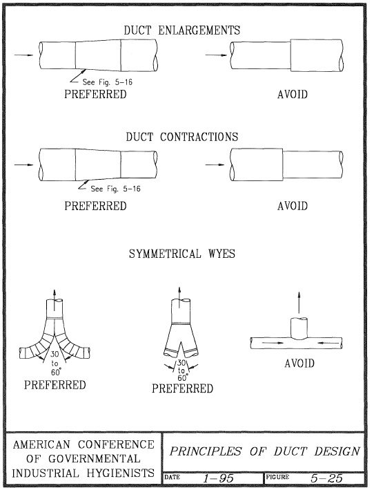
Reducers:
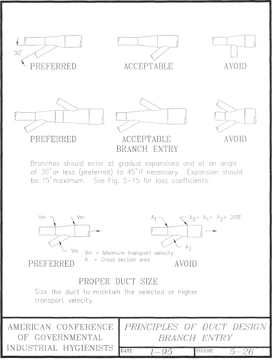
Sharp-step-type reducers are to be avoided. Smooth tapering reducers should be considered. Also, ensure that the size of the duct is expanded prior to connecting branches and not after the connecting branch.
Dampers are essential in CV (constant volume) systems, including self-balancing methods. The use of dampers ensures that we get the required air flow as per design at each branch.

Fig: Principles Of Duct Design-Duct Enlargements(ACGIH Industrial Ventilation-23 Edition)

Fig: Principles Of Duct Design-Duct Enlargements(ACGIH Industrial Ventilation-23 Edition)
Visit blogs to learn more about the critical features of clean air system design and air pollution control systems created by Filter On India.
Filter On India has been working towards “Mission Zero Pollution” for the last 40+ years as a clean air solutions partner for industries. We specialize and have expertise in welding fumes, oil mist, coolant mist, dust collection, soldering, laser marking, laser cutting, plasma cutting, fumes in fastener manufacturing, ball point tip manufacturing, oil quenching, kitchen fumes, etc. Filter On has 70+ clean air solutions, so you can contact us for more information about our solutions. You can reach us through the web or visit us at our corporate office at Pune and our virtual locations at Delhi, Bangalore, Ahmadabad, Hyderabad, or Chennai locations.