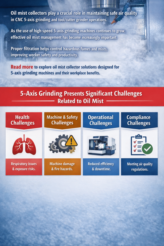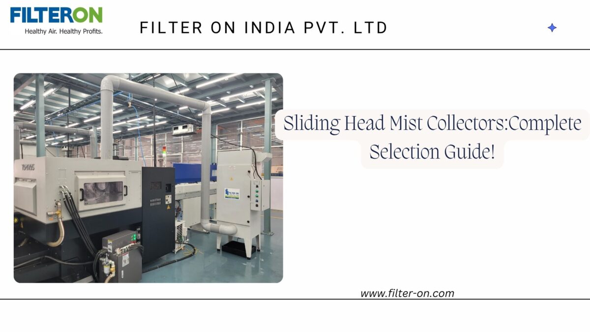
Oil mist collectors for sliding-head machines precisely control sliding-head mist and fumes. These fumes are very hazardous to health, as these fumes can impact workers and make the work environment polluted. As a result, to control fumes from sliding-head machines, oil mist collectors must have some of the key features that we will be discussing here in this blog post.
Why and What Should You Look For In Sliding Head Mist Collectors:
When we consider a sliding head mist collector for the first time, we need to look at some of the key factors, which are listed below. These reinforce your decision to purchase a right sliding head mist collector.
- Purpose: Sliding head mist collectors are essential for extracting high-volume, sub-micron oil mists from Swiss-type CNC lathes using high-pressure neat oils.
- Specialization: These machines require compact and efficient filters due to their operation in tight enclosures with thick, ultra-fine mist.
- Filtration Efficiency: Look for oil mist collectors with electrostatic precipitators (ESPs) that can capture 95–99% of particles down to 0.3 to 0.5 microns, as other types of standard filters are inadequate.
- Filter Type: Manufacturers like Filter ON provide specialized ESP filtration solutions tailored for neat oil processing in sliding head lathes.
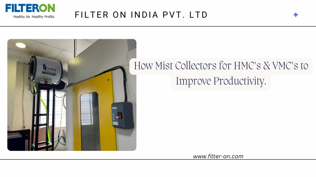
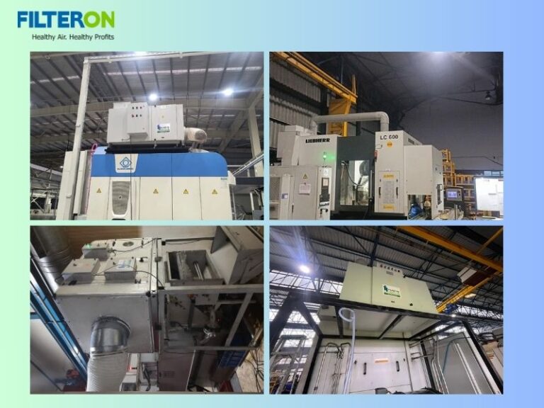
- Mounting of sliding head mist collectors: Choose units with a compact design, able to be directly top-mounted onto machine enclosures or pillar mounted near sliding head machines, optimizing shop-floor space while maintaining high capacity (300 m³/hr to 2000 m³/hr). Combining multiple machines in a common larger size Mist Collector system also would save space.
Role of ESP in Sliding Head Mist Collectors:
Electrostatic precipitation is one of the finest technologies to capture harmful particles from sliding head machining Mist & Fumes and filter them and provide clean air back to the work environment. ESP plays a very vital role in sliding head mist collector filtration, as it has the following features:
- Minimal Power Cost: Unlike the other technologies, ESPs work in very low power due to their innovative electrostatic technology, which uses less power while working.
- Zero Cost on Filter Replacement: As sliding head mist collectors use ESP cells and their pre- as well as post-filters, all are washable in nature. You can use it for as long as you require by just periodic cleaning based on your usage pattern so that your replacement cost for filters is saved due to this technological advancement.
- Minimal Pressure Drop: The significant aspect of ESP-based sliding head mist collectors is that they have a limited pressure drop, which is almost 50% less than equivalent capacity Media type filters.
Parameters to decide on a sliding head mist collector:
- Checking the make & model: When selecting a sliding head mist collector, it is essential to check the make and model of the sliding head machine. This information helps determine the appropriate capacity for the mist collector, as different makes and models of sliding heads have unique arrangements for mist generation and discharge. Our (Filter ON’s) sliding head mist collector is compatible with the following brands of sliding head machines:
- Citizen
- Star
- Tornos
- Tsugami
- Rollomatic
- Rod Diameter: In sliding head machines, rod diameter has a considerable imp act on machining processes such as cutting forces, spindle speed, coolant flow, and oil mist volume. Larger rod diameters require higher coolant flow and longer cutting cycles, resulting in more coolant and oil mist. Efficient mist collectors gather airborne mist at its source, improving air quality and safety and eliminating slippery leftovers. The ideal mist collector size is determined by coolant type, pressure, enclosure volume, spindle speed, and duty cycle. Thus, for best mist collector performance, entire machining conditions must be evaluated rather than just rod diameter.
- Oil Pressure: When cutting oil or coolant is supplied under high pressure, it atomizes into fine droplets that create oil mist. Increased oil pressure correlates with more oil atomization, leading to greater airborne mist concentration and the potential need for more efficient mist collectors. For instance, at low pressure (5–20 bar), standard mist collectors suffice; at medium pressure (20–50 bar), higher airflow and filtration are necessary; and at high pressure (50–150+ bar), high-performance collectors are required due to the large amounts of fine mist generated. Sliding head machines utilize high-pressure cutting oil systems to enhance chip breaking, tool cooling, and dimensional accuracy, necessitating careful consideration of oil pressure alongside other factors such as oil flow rate, spindle speed, and machine enclosure size when choosing mist collectors.
- Material Used: Common materials used in sliding head machining include stainless steel (SS), aluminum, brass, copper, titanium, carbon steel/alloy steel, and engineering plastics. Stainless steel, particularly grades like SS 303, 304, and 316, is often used for medical parts and automotive components, generating fine oil mist due to high cutting resistance. Aluminum, used in electronics and aerospace, produces significant mist at high spindle speeds. Machining brass and copper produces oil mist and fine chips, but titanium requires more oil at higher temperatures, which increases mist formation. Carbon steel and alloy steel produce moderate- to high-mists, depending on the conditions. The choice of material influences various factors, such as oil temperature and pressure, cutting speed, and chip formation, which affect mist production. For instance, machining stainless steel with high-pressure oil results in finer, more abundant mist compared to brass at lower parameters. All of these materials significantly influence the level of mist exposure generated by sliding head machines.
- Requirement of Layout: In the case of multiple sliding head machines installed at the plant, one can think of a centralized system for sliding head mist collection, i.e., the layout of the entire plant or the area in which sliding head machines are installed is required to optimize fume and mist generation from there to effectively capture and filter fumes and mists and provide workers with a cleaner work environment.
If your Sliding head machines operate without proper oil mist control, efficiency is being lost daily.
Evaluate your setup or consult an expert like Filter ON India to select the right system as per requirement, budget and scope. Contact us to learn more….
Frequently Asked Questions:
1. Why is a mist collector required for a sliding head machine?
Ans: Sliding head machines operate at high spindle speeds and often use high-pressure cutting oil or coolant. This combination produces fine oil mist that can escape into the workplace. A mist collector captures these airborne particles, improving air quality, operator safety, machine cleanliness, and overall productivity.
2. Which type of mist collector is best for a sliding head machine?
Ans: The ideal mist collector depends on factors such as coolant type, oil pressure, spindle speed, machine enclosure, and production hours. For machines using neat cutting oil and generating very fine submicron mist, an Electrostatic Precipitator (ESP) is often an excellent choice because of its high filtration efficiency and oil recovery capability.
3. Can one mist collector serve multiple sliding head machines?
Ans:Yes, provided the total airflow requirement (CFM or m³/h), duct design, and machine operating schedule are properly calculated. Centralized systems are suitable for multiple machines, while individual units provide dedicated extraction.
4. Does a mist collector recover cutting oil?
Ans:Yes. Many ESP-based and centrifugal mist collectors separate oil from the air stream, allowing recovered oil to drain back into a collection tray. This reduces oil wastage and helps keep the work area clean
5. How often should a sliding head mist collector be maintained?
Ans: Maintenance frequency depends on machine utilization, oil type, filtration technology, and production hours. Routine inspection and cleaning help maintain airflow, filtration efficiency, and equipment life. Typical cycles vary from once in 6 weeks to once in 4 months.