In our previous article. we discussed the key parameters that need to be considered for the right fan selection. We have also checked what a VFD is, i.e., a variable frequency drive. As the role of VFD is an important parameter for our fan selection, Filter On is always considered. “Optimizing clean air systems: The role of VFD for fans” is important when designing clean air systems, so we have discussed here the role of VFD in improving our clean air system design.
The power consumed by any fan The blower depends on the air flow and total static pressure. Air flow depends on suction hood and enclosure design, while static pressure loss depends on ducting. layout and filter pressure drop. Designers must consider these factors to minimize motor capacity overdesign.
How air flow and static pressure are crucial factors in power consumption for a system.
Air Flow:
Air flow depends on the suction, hood design and enclosure arrangement. The main purpose is to capture the fumes before they spread into the environment.
Static Pressure:
Static pressure loss depends on ducting layout (diameter, conveying duct velocity, length, and number of fittings like elbows, tees, etc.) as well as filter pressure drop.
The Designer’s Role In System Design: Role of VFD for Fans
The designer needs to keep some margin considerations for air flow (to accommodate any minor additions needed) as well as static pressure (to accommodate a few changes in ducting layout and changes in filter pressure loss over time). Thus, the Blower selected especially in a centralized fume extraction system is overcapacity (both in air flow and static pressure) to accommodate these changes.
How is VFD useful for clean air systems?
Before going into this aspect, One has to understand the fan laws (especially for centrifugal fans). The understanding of fan laws will guide us about how to use VFD to optimize the power consumption of a blower in a fume extraction system without compromising the required performance.
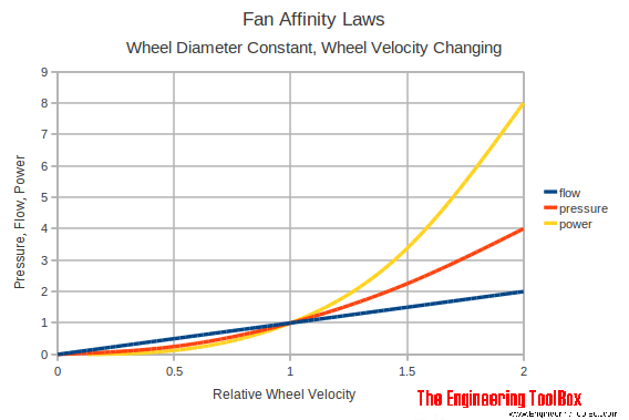
There are three fan laws to be followed.:
The first fan law states that
The changes in air flow rate of the fan are proportional to the changes in speed. the impeller. For example, if the impeller speed is increased by 10%, then the The air flow rate will also increase by 10%.
The second fan law states that
The changes in total static pressure in the ventilation system will increase by the square of the changes in impeller speed of the fan. For example, if the impeller If the speed of the fan is increased by 10%, then the total static pressure will increase by 21%.
The third fan law states that the
The changes in horse power required by the fan to turn the impeller will increase by the cube of the changes in impeller speed of the fan. For example, if the impeller speed is increased by 10%, then the horsepower required to turn on The impeller will increase by 33.1%.
By using these fan laws, one can effectively deploy the VFD, PLC, and actuated damper combination to achieve huge savings in the running cost of a fume extraction system.
First, the system's initial set point should be adjusted to 100% of the required value based on real site conditions. Air flow is controlled at each station based on design estimates using manual dampers and a VFD. As a result, the system pulls the exact amount of electricity required. The initial configuration can save around 10–15% of electricity.
Because the blower is a centrifugal device, reducing the RPM results in a corresponding drop in airflow, but the power savings are in cube proportion to the RPM reduction. Thus, a 10% drop in RPM results in a 10% reduction in airflow, but a 19% decrease in power!
For optimal part load efficiency, A VFD must be paired with actuated dampers at each drop and a PLC controller. Running station-actuated dampers will remain open, while non-operational Station dampers will be closed by merging actuator and cell operations.
The signal from each damper (ON/OFF) is sent to the PLC controller, which decreases or raises the RPM of the motor based on the logic incorporated into the VFD. If half of the stations are closed, the RPM is lowered by half, resulting in a 50% reduction in air flow. In such a circumstance, the electricity savings might be up to 75%!
Thus, significant power savings can be achieved in partial load conditions. which can pay back for the additional investment costs for VFD and PLC in many cases.
Filter On India has been working towards “Mission Zero Pollution” for the last 40+ years as a clean air solutions partner for industries. We specialize and have expertise in welding fumes, oil mist, coolant mist, dust collection, soldering, laser marking, laser cutting, plasma cutting, fumes in fastener manufacturing, ball point tip manufacturing, oil quenching, kitchen fumes, etc. Filter On has 70+ clean air solutions, so you can contact us for more information about our solutions. You can reach us through the web or visit us at our corporate office at Pune and our virtual locations at Delhi, Bangalore, Ahmadabad, Hyderabad, or Chennai locations.