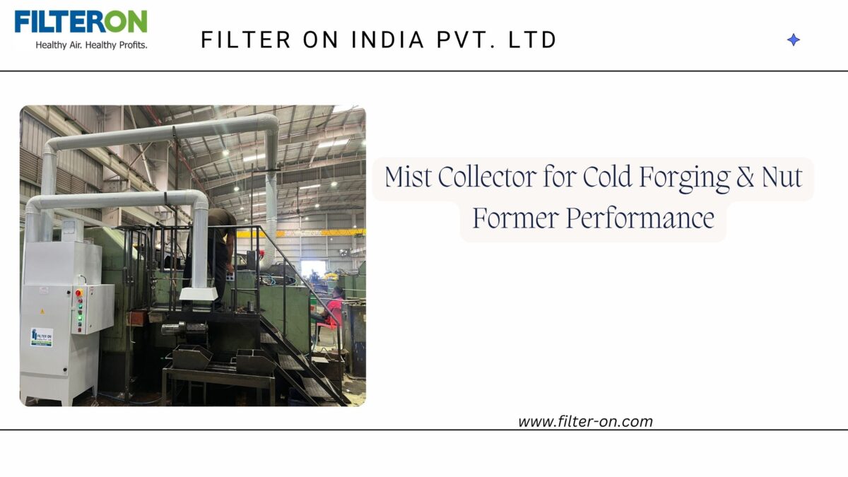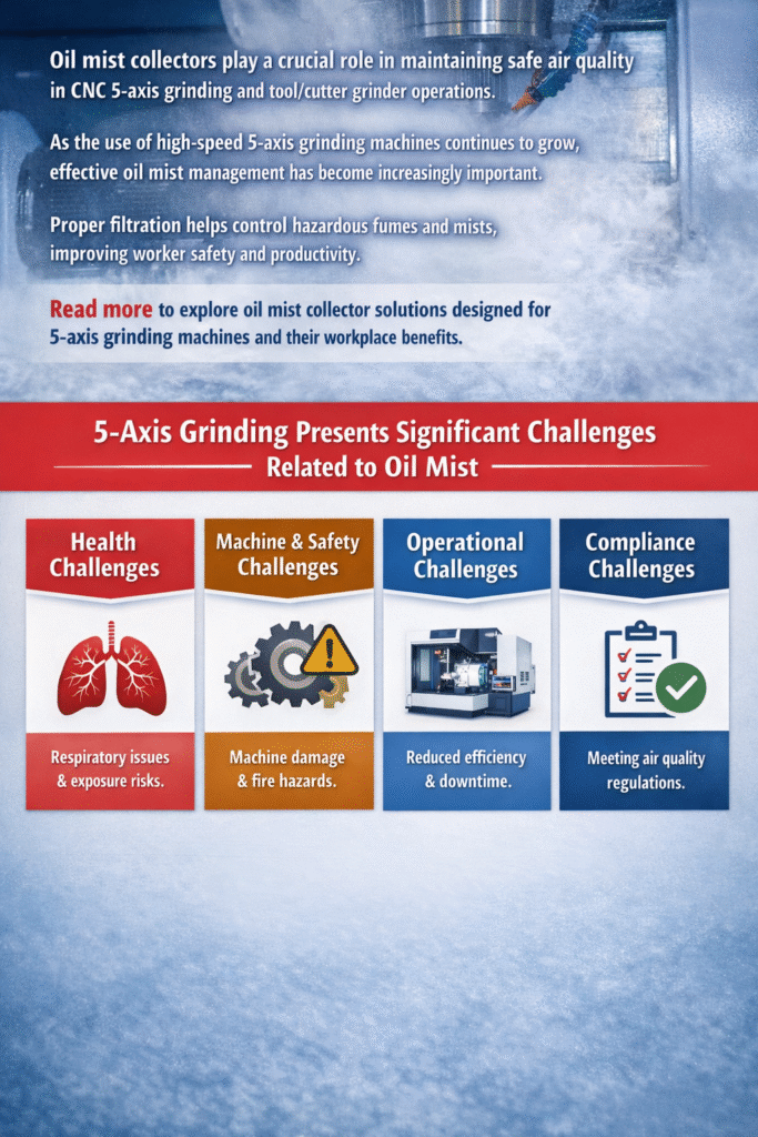
Mist generated during machining in HMCs and VMCs spreads throughout the work environment, creating an unhealthy atmosphere that can lead to various health issues for machine operators. Mist Collectors for HMC's & VMC's provide an effective and efficient solution by capturing coolant and oil mist at the source, helping create a cleaner, safer, and mist-free machining environment. This not only improves worker productivity but also contributes to better indoor air quality and compliance with workplace safety standards. In this blog post, we will discuss "How Oil Mist Collectors Improve Productivity in VMCs and HMCs", covering key aspects such as coolant mist control, filtration efficiency, and oil recovery.
Controlling the mist using Mist Collectors for HMCs & VMCs:
When we think of mist control in HMCs and VMCs, we need to look into coolant mist control, as HMCs and VMCs require coolant to run, and they generate a high amount of mist during operations. To control the coolant mist, we need to know about the following factors:
- Application Details: It is important to understand the specific application context.
- Type of oil/coolant:It is important to know whether neat cutting oil or water-soluble coolant is used, as this information is necessary for recommending the appropriate oil mist collector.
- Machining oil and coolant pressure: Machining oil and coolant pressure (expressed in bar) are required to determine the oil-mist collector capacity and size.
- Size of Door Opening: The size of the door opening is needed when we consider the oil mist collector, as the size of the door is required for maintenance purposes.
- Cutting Chamber Size: Cutting chamber size is in LXWXH parameters required to measure how much mist can be generated while cutting the workpiece.
- Coolant Type: When we consider coolant mist collectors for HMC and VMC, the type of coolant is necessary to be checked, as there are flood-type and micromist-type coolants. It is important because both of these types generate different mist characteristics, depending on the type.
Key benefits of mist collectors for VMC's & HMC's
- Improved Air Quality for Operators
Mist collectors for HMC’s & VMC’s improve air quality for operators by reducing the airborne coolant mist and smoke. It creates a cleaner and healthier workspace and minimises health issues among workers, such as breathing discomfort and eye irritation as well as long-term health hazards like bronchitis, lung cancer, COPD, etc.
- Reduced Machine Downtime
Mist collectors for HMCs and VMCs improve air quality for operators, thus reducing machine downtime by preventing oil mist build-up inside machine enclosures. It also reduces maintenance interruptions by improving mist exposure. It keeps CNC machines operating efficiently for longer hours by reducing the smoke and mist.
- Better Visibility During Machining
When operators are doing machining work, mist spreads all over inside CNC, VMC and HMC machines, especially inside enclosures. Mist collectors remove this fog and mist from enclosures. It helps operators to monitor the machining process clearly, and as a result, it improves accuracy and operational safety.
- Longer Machine Life
For longer machine life, a mist collector for HMC’s and VMC’s prevents sticky oil deposits on electrical panels and machine parts. It also reduces wear and tear on sensitive components. It protects bearings, sensors and control systems.
- Lower Maintenance Expenses
The maintenance costs of HMC’s and VMC’s are high due to mist exposure and periodic wear and tear; for that reason, there is a need for a mist collector that is beneficial for cleaning requirements around machines and shop floors. It also reduces coolant quality issues.
- Improved Worker Productivity
For increasing productivity among workers, a mist collector will surely help by creating cleaner environments, which improves the comfort and morale of operators. As exposure to oil mist is controlled by using a mist collector, there will be fewer health-related interruptions and absenteeism. These will help operators focus better on machining operations, which ultimately improves workers’ productivity.
- Enhanced Coolant Recovery
Mist collectors for HMC’s & VMC’s will help in oil and coolant recovery as well; they capture coolant that can be drained back into the machine. They help in reducing coolant wastage. It also improves operational efficiency and cost savings.
- Compliance with Industrial Safety Standards
Mist collectors for HMC’s & VMC’s machines contribute to maintaining safer workplace conditions. These mist collectors comply with OSHA, CPCB, and factory safety regulations, ensuring adherence to current standards. By implementing a standard mechanism to control mist, they enhance the company’s reputation and readiness for audits.
- Cleaner Overall Shop Environment
Mist collectors for HMC’s & VMC’s clean the shop environment by collecting harmful mist, which prevents oil deposits on floors, walls and lighting fixtures. It reduces slip hazards in machining areas. It maintains professional, organised production spaces very well.
If your HMC’s & VMC’s machines operate without proper oil mist control, efficiency is being lost daily.
Evaluate your setup or consult an expert like Filter ON India to select the right system as per requirement, budget and scope. Contact us to learn more….
Frequently Asked Questions:
1. Why do VMCs and HMCs require oil mist collectors?
Ans: VMCs and HMCs generate coolant mist during machining operations. Oil mist collectors capture these airborne particles, helping maintain cleaner air, improve operator safety, and protect machine components.
2. How do oil mist collectors improve productivity in CNC machining?
Ans: By reducing machine contamination, improving visibility inside enclosures, and minimizing maintenance requirements, oil mist collectors help reduce downtime and improve overall productivity.
3. Can oil mist collectors help extend machine life?
Ans:Yes. Oil mist collectors prevent oil deposits from accumulating on electrical panels, sensors, and machine components, reducing wear and maintenance costs while extending equipment life.
4. Which type of oil mist collector is best for VMC and HMC machines?
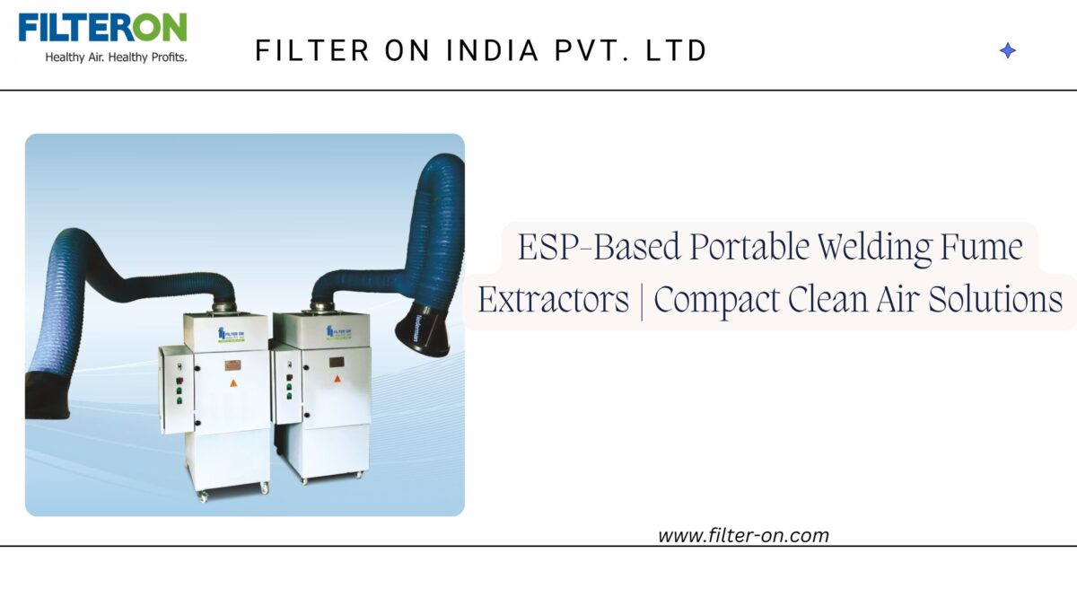
Ans:The right solution depends on the coolant type, mist volume, and machining process. ESP-based oil mist collectors are often preferred for their high efficiency, washable filters, and low operating costs in case of neat cutting oil. For soluble coolants,centrifugal type Mist Collector is the optimum choice.
VMCs and HMCs generate coolant mist during machining operations. Oil mist collectors capture these airborne particles, helping maintain cleaner air, improve operator safety, and protect machine components.